

Power Transformers Background
Power Transformers are used within AC power distribution systems to increase or decrease the operating voltage to achieve optimum transmission efficiency and to provide electrical isolation between power circuits. Power is transferred via mutual induction between windings of the transformer, with the voltage being transferred from primary to secondary at the ratio of primary to secondary winding turns in accordance with the term Vs/Vp = Ns/Np.
Power transformers are used to transfer power from the power station to the substation; this is because power generation is very efficient at low voltages, while power transmission is more efficient at high voltages. This is because the ohmic losses (commonly known as ‘I 2R’ or ‘copper’ losses) are significant over long distances, so power is transferred at a higher voltage with corresponding lower current.
An additional benefit of reducing the I2R losses during transmission is that the conductor cross-sectional area can be minimised. This does not come without the complications of handling high voltages, yet the advantages in efficiency outweigh the disadvantages of high voltage design. As power levels of power transformers are now in the multiple MVA rating region, losses must be kept to an absolute minimum. Even a 1% loss of a 10MVA transformer will result in a loss of 100kW
Basic Theory
If one of two adjacent windings is supplied with an alternating current source, this alternating current generates a continually changing flux surrounding the winding that induces an EMF into the second winding. With a short circuit or low impedance load connected across the second winding, current will flow in the secondary circuit.
If the two windings were only linked with air i.e. placed in close proximity to each other, the amount of flux linkage would not be enough to produce an efficient transformer and there would be a large amount of flux leakage. However, by adding a low reluctance ‘core’ between both windings to ensure that the maximum amount of flux is passed through the secondary, high transformer efficiency can be achieved.
So, it is from this theory we have the basic building blocks of the transformer as follows
- An AC source
- Primary winding
- Low reluctance path for flux coupling (Core)
- Secondary winding
Ideal Transformer
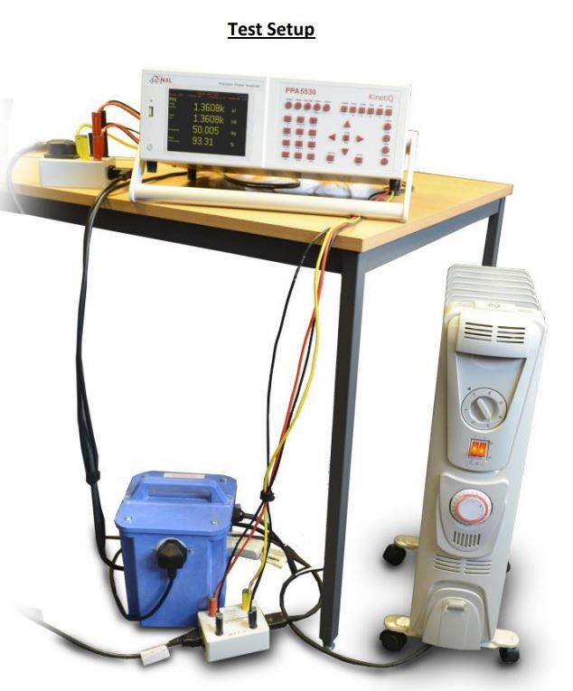
An ideal transformer would exhibit zero losses, i.e. no copper loss, no core loss or stray loss. The efficiency of this ‘ideal’ transformer would be 100% but in reality, this doesn’t exist for reasons we will explain in the following text. To support the theory, we will also use a high accuracy precision power analyser to measure the losses in a real transformer. This will illustrate the importance of certain aspects of transformer loss testing instrumentation and how the Newtons4th PPA5530 offers an accurate solution to this field of testing.