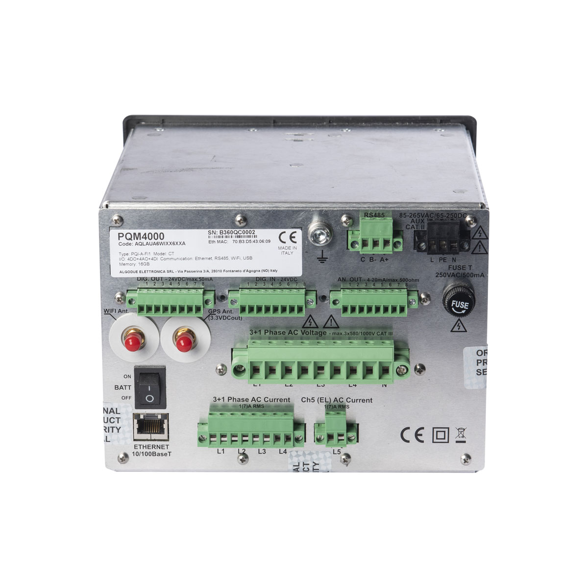
Power Quality Analyzer | PQM4000

Power Quality Analyzer | PQM4000

Price range: R89,014.00 through R104,956.00 ex vat

Power Quality Analyzer – Overview

PQM4000 is a high-end power quality analyzer, able to monitor and record major power quality parameters. It provides accurate measurement, voltage, and current characteristics are monitored according to Class A specifications. At the same time, it acts as an event/fault recorder, capable to store a high number of voltage events and disturbances, frequency variations, inrush current, etc. Additional PQ data can record Flicker, Unbalance, Harmonics,  Inter-harmonics, and Mains Signaling. It also provides standard power measurement data for three-phase systems.

Extra voltage and current measurement channels give the possibility to monitor Neutral Potential and Earth Leakage current. The PQM4000 is available in 2 models: one for external CTs with 1 or 5A inputs and another one for current clamps with 1 or 3V inputs. In this way, maximum flexibility is granted even to existing plants.

The powerful recording features give the possibility to capture and record all types of standard and PQ data simultaneously. All this information can be recorded for a long period due to the high memory capacity. This way a complete EN 50160 analysis can be performed. Events and disturbances also provide waveform recording together with RMS values. Recordings can be transferred in different ways: users can download them directly through a web interface, or an automatic data upload can be scheduled to a remote server. Alternatively, data can be transferred to a USB flash drive.

Power Quality Analyzer PQM4000 Features

• Two different models – for CTs or current clamps
• Harmonics and inter-harmonics measurement
• Data recording for further EN 50160 analysis
• Data recorded in standard PQDIF and CSV file formats
• Embedded webserver
• Communication on Ethernet, RS485 and WIFI
• USB host port for data transfer
• Integrated GPS for accurate timing
• 1024×600 high-resolution TFT display with capacitive touch
• Internal rechargeable backup battery
• Class A for voltage and current characteristics according to
IEC/EN 61000-4-30:2015 Ed.3

Datasheet 


Description

Power Quality Analyzer – PQM4000

Specification

POWER SUPPLY
Auxiliary power voltage: 100 – 240 VAC | 50/60 Hz | 65-250 VDC |19 – 60 VDC (on request)
Auxiliary power consumption: 15 W
Fuse (according to the power supply): 250 VAC / 500 mA T type delayed
(35 A breaking capacity) with
100 – 240 VAC | 50/60 Hz | 15 W | 65 – 250 VDC
250 VAC / 3 A T type delayed with 19 – 60 VDC
Backup battery: Li-Ion | 2500 mAh (>15 min autonomy)
MEASUREMENT INPUTS
Voltage inputs for direct connection: Phase-neutral (L-N): max 580 V RMS CAT III
Phase-phase (L-L): max 1000 V RMS CAT III
Voltage input crest factor: 2
CT inputs (only CT instrument model): max: 7 A RMS for FS = 5 Ap
max: 1.2 A RMS for FS = 1 A
CT burden (only CT instrument model): 0.04 VA
Current clamp inputs (only CLAMP instrument model): max: 1.5 V RMS for FS = 1 V,
max: 4.5 V RMS for FS = 3 V
Current input crest factor (only CT instrument model): 3
Input impedance (for direct voltage inputs):  > 6 MΩ
Frequency range: 42.5 – 57.5 Hz | 51 – 69 Hz
Frequency reference channel: Phase 1/Line 12 voltage
Sampling: Simultaneous, 51.2 kHz @50 Hz
ACCURACY
Three phase voltage: ±0.1% Un over 10 … 150% Un range
4th voltage: ±0.2% measurement
Currents: ±0.2% measurement (device)
Powers: ±0.2% measurement
Frequency: ±10 mHz
Harmonics: Class 1 (IEC/EN 61000-4-7)
Internal clock (RTC): < 1 s for 24h period without synchronization
< 5 ms with GPS synchronization
< 500 ms with NTP synchronization
Active energy (FS = 5 A): Class 0.2S, compliant to IEC/EN 62053-22
Reactive energy: Class 1, compliant to IEC/EN 62053-23
I/O CHANNELS
Digital inputs: 4 optoisolated 24 VDC
Digital input delay time (1 – 4): max: 10 ms
Digital input consumption (1 – 4): max: 7 mADC
Analogue outputs: 4 optoisolated 4 – 20 mADC / max load 500 Ω
Analogue output reaction time: max: 200 ms
Digital outputs: 4 passive optoisolated 24 VDC / max 50 mA
Digital output reaction time (DO in Alarm mode): max: 1 s
Digital output pulse length (DO in Pulse mode): 50 ±2 ms ON time
MEMORY
System memory: 128 MB Flash, 256 MB RAM
Recording memory: 16 GB
COMMUNICATION
Ethernet ports: 2 Auto MDIX RJ45 10/100 Base Ethernet
RS485 port: 1 optoisolated, 4800 – 115200 bps
GPS port: 1 SMA female connector
WIFI port: 1 SMA male connector
Protocols: HTTP | FTP | SFTP | NTP | NMEA | Modbus RTU/TCP
RTC SYNCHRONISATION
Synchronization system: NTP and/or GPS
ENVIRONMENTAL CONDITIONS
Installation and use code: PQI-A-FI1-H
Operating temperature (limit range): -25 – +55°C (FI1, 3K6)
Storage temperature: -25 – +75°C (2K3)
Relative humidity: 95% max without condensing
Altitude: max: 2000 m AMSL
MECHANICAL CHARACTERISTICS
Mounting: Panel mount 192×144 DIN size
Size: Front (LxH): 191×143 mm
Rear (LxHxD): 183x135x190 mm
Weight: 1400 g
DIRECTIVE AND STANDARD COMPLIANCE
Directive: 2014/53/EU
Product compliance: IEC/EN 62586-1 | IEC/EN 62586-2
Safety: EN 61010-1
Pollution degree: 2 (EN 61010-1)
Protection degree: IP40 front panel, IP20 rear
Protection against mechanical impacts: IK06

The VERSIONS column shows the available parameters (x) according to the instrument version.
The APPLICATIONS column indicates all parameters which can be displayed, recorded or involved in the event detection process, refer to the following detailed description:

  •  Real-time: real-time parameters are shown in a Web server (Real-Time and Graphics sections) as well as in Modbus TCP by a reading command. In the case of Demand MAX values, data is stored with the timestamp (S).
  • Events: parameters monitored for event capture.
  • Logging: parameters programmable according to the logging type:
    • M=Min/Avg/Max value logging,
    • D=Demand value logging,
    • E=Energy counter logging.
  • Analogue outputs: parameters to be associated with analogue outputs.
  • Digital outputs: parameters to be associated with digital outputs, according to the mode: A=Alarm, P=Pulse.

All the parameters indicated in the APPLICATIONS column are available according to the set wiring mode.

VERSIONS APPLICATIONS
PARAMETERS Basic DMD ENH Real-time Events Logging Analog
outputs
Digital
outputs
Voltages (ULN, ULL, U4N, U4L) x x x x x M x A
System Voltage (U?) x x x x M x A
Phase Sequence x x x x M
System Frequency (F) x x x x x M x A
Currents (IL) x x x x x M x A
Line 4 Current, Earth Leakage, System Current (I4, I5, I?) x x x x M x A
Powers (PL, P?, SL, S?, QL, Q?) x x x x M x A
Power Factors (TPFL, TPF?, DPFL) x x x x M x A
Voltage Symmetrical Components (U0, U1, U2) x x x x M x A
Voltage Unbalance Ratios (u0, u2) x x x x x M x A
Current Symmetrical Components (I0, I1, I2) x x x x M x A
Current Unbalance Ratios (i0, i2) x x x x M x A
Voltage Underdeviations (UdevULN, UdevULL) x x x x M x A
Voltage Overdeviations (OdevULN, OdevULL) x x x x M x A
Short Term Flickers (PstL) x x x x M
Long Term Flickers (PltL) x x x x x M
Voltage Total Harmonic Distortions (THDULN, THDULL) x x x x x M x A
Voltage Even & Odd Harmonic Distortions (eHDULN, oHDULN, eHDULL, oHDULL) x x M x A
Current Total Harmonic Distortions (THDIL) x x x x M x A
Phase 4 Current Total Harmonic Distortion (THDI4) x x x A
Current Total, Even & Odd Demand Distortions (TDDIL, eDDIL, oDDIL) x x M x A
K Factors (KL) x x x x M x A
Mains Signallings 1…5 (ULN-MS1…5) x x x x x M
Current Demands (ILDMD, I4DMD, I5DMD, I?DMD) x x D A
Active Power Demands (+PLDMD, -PLDMD, +P?DMD, -P?DMD) x x D A
Reactive Power Demands (+QLDMD, -QLDMD, +Q?DMD, -Q?DMD) x x D A
Apparent Power Demands (+SLDMD, -SLDMD, +S?DMD, -S?DMD) x x D A
True Power Factor Demands (+TPFLDMD, -TPFLDMD, +TPF?DMD, -TPF?DMD) x x D A
Current Demand MAX (ILDMDMAX, I4DMDMAX, I5DMDMAX, I?DMDMAX) x S
Active Power Demand MAX (+PLDMDMAX, -PLDMDMAX, +P?DMDMAX, -P?DMDMAX) x S
Reactive Power Demand MAX (+QLDMDMAX, -QLDMDMAX, +Q?DMDMAX, -Q?DMDMAX) x S
Apparent Power Demand MAX (+SLDMDMAX, -SLDMDMAX, +S?DMDMAX, -S?DMDMAX) x S
True Power Factor Demand MAX (+TPFLDMDMAX, -TPFLDMDMAX, +TPF?DMDMAX, -TPF?DMDMAX) x S
Voltage Harmonics & Interharmonics (ULN Ha&IHa, ULL Ha&IHa) x x x x M x A
Current Harmonics & Interharmonics (IL Ha&IHa) x x x x M x A
UL Angle Relative to U1 – On Fundamental (AngU1U2, AngU1U3, AngU1U4) x x x x x A
IL Angle Relative to U1 – On Fundamental (AngU1I1, AngU1I2, AngU1I3, AngU1I4, AngU1I5) x x x x x A
Imported & Exported Active Energy (+kWh, -kWh) x x x x x E P
Imported & Exported Apparent Energy – IND/LAGG. (+kVAh-L, -kVAh-L) x x x x x E P
Imported & Exported Apparent Energy – CAP/LEAD. (+kVAh-C, -kVAh-C) x x x x x E P
Imported & Exported Reactive Energy – IND/LAGG. (+kvarh-L, -kvarh-L) x x x x x E P
Imported & Exported Reactive Energy – CAP/LEAD. (+kvarh-C, -kvarh-C) x x x x x E P

Power Quality Analyzer – PQM4000

Additional information

Option

BASIC FOR CTs (not included), DMD FOR CTs (not included), ENH FOR CTs (not included), BASIC FOR CLAMPs (not included), DMD FOR CLAMPs (not included), ENH FOR CLAMPs (not included)

Brand

Algodue Electronica

Algodue Electronica is a specialist in Electricity Metering Systems. They have over 30 years of experience in the field of energy management. Quality, experience and flexibility to offer the best solution and to achieve customer satisfaction.
Algodue logo

Reviews

There are no reviews yet.

Be the first to review “Power Quality Analyzer | PQM4000”