Description
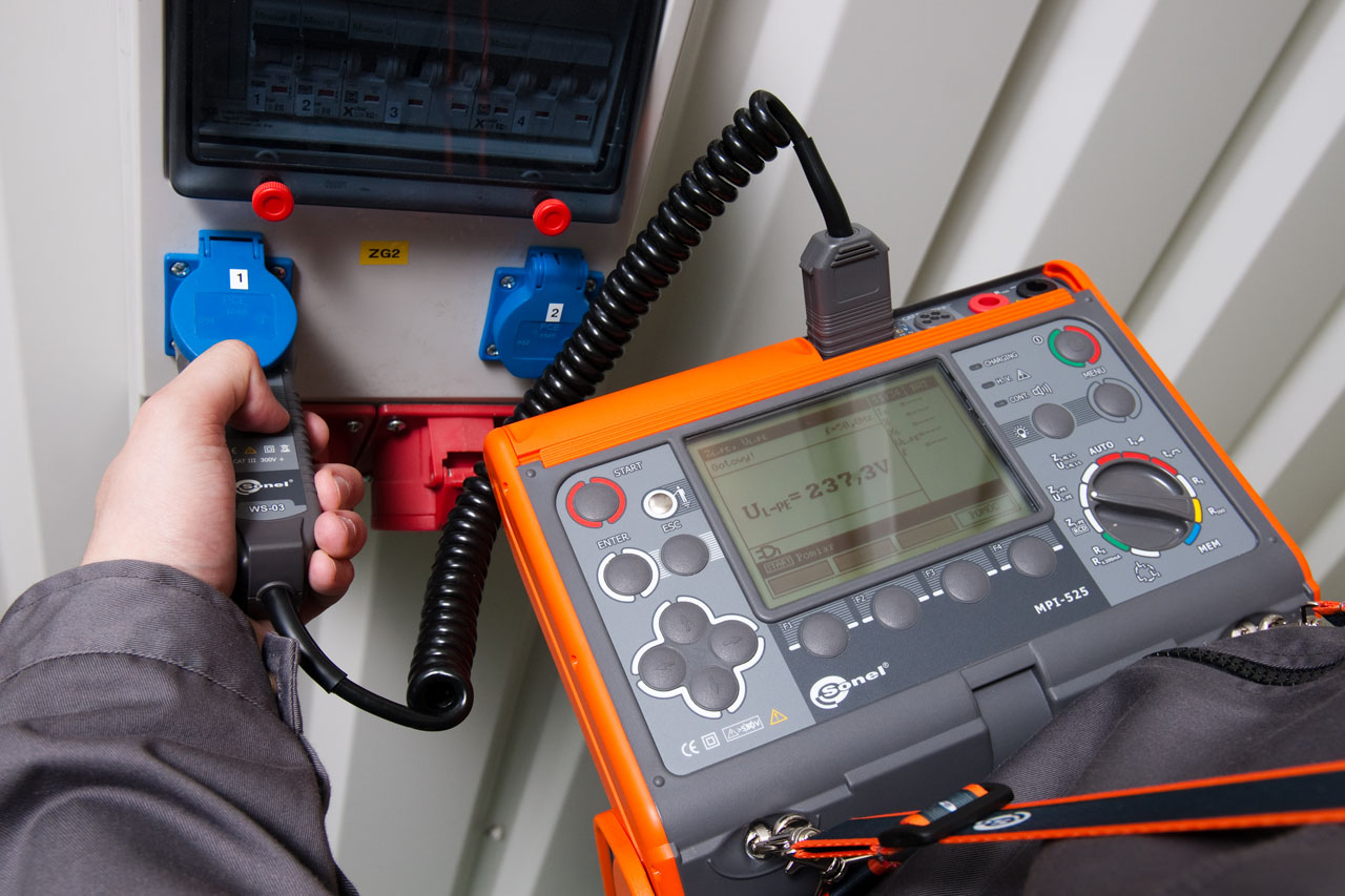
Electrical Installation Multi-function Meter MPI-525
Technical Specifications
Rated operational conditions:
– Operation temperature 0 – +50°C
Electric security:
– Type of insulation: double, according to PN-EN 61010 – 1 And IEC 61557, EMC
– Measurement category: IV 300 V acc. to PN-EN 61010 – 1
– Protection class acc. to PN-EN 60529: IP54
Measurement of short circuit loop impedance ZL-PE, ZL-N, ZL-L
Test current: 23/40 A; Measuring range acc. to IEC 61557: 0,13 – 1999,9 Ω (for 1.2 m test lead):
| Display range |
Resolution |
Accuracy |
| 0,000 – 19,999 Ω |
0,001 Ω |
±(5% m.v. + 30 digits) |
| 20,00 – 199,99 Ω |
0,01 Ω |
±(5% m.v. + 30 digits) |
| 200,0 – 1999,9 Ω |
0,1 Ω |
±(5% m.v. + 30 digits) |
- Rated voltage: 95 – 270 V (for ZL-PE and ZL-N) and 95 – 440 V (for ZL-L)
- Frequency: 45 – 65 Hz
Measurement of short circuit loop impedance ZL-PE in RCD mode
Test current: 15 mA, measuring range acc. to IEC 61557: 0,50 – 1999 Ω
| Display range |
Resolution |
Accuracy |
| 0,00 – 19,99 Ω |
0,01 Ω |
±(6% m.v. + 10 digits) |
| 20,0 – 199,9 Ω |
0,1 Ω |
±(6% m.v. + 5 digits) |
| 200 – 1999 Ω |
1 Ω |
±(6% m.v. + 5 digits) |
- Rated voltage: 95 – 270 V
- Frequency: 45 – 65 Hz
Measurement of earth resistance RE
Measuring range acc. to IEC 61557-5: 0,50 Ω -1999 Ω
| Display range |
Resolution |
Accuracy |
| 0,00 – 9,99 Ω |
0,01 Ω |
±(2% m.v. + 4 digits) |
| 10,0 – 99,9 Ω |
0,1 Ω |
±(2% m.v. + 3 digits) |
| 100 – 999 Ω |
1 Ω |
±(2% m.v. + 3 digits) |
| 1,00 – 1,99 kΩ |
0,01 kΩ |
±(2% m.v. + 3 digits) |
Insulation resistance measurements
Measuring range acc. to IEC 61557-2:
- For UN= 50 V: 50 kΩ- 250 MΩ
- UN = 100 V: 100 kΩ – 500 MΩ
- UN = 250 V: 250 kΩ – 999 MΩ
- For UN = 500 V: 500 kΩ – 2 GΩ
- UN = 1000 V: 1 MΩ – 9,99 GΩ
- UN = 2500 V: 2,5 MΩ – 9,99 GΩ
| Display range * |
Resolution |
Accuracy |
| 0,00 – 1999 kΩ |
1 kΩ |
±(3% m.v. + 8 digits) |
| 2,00 – 19,99 MΩ |
0,01 MΩ |
±(3% m.v. + 8 digits) |
| 20,0 – 199,9 MΩ |
0,01 MΩ |
±(3% m.v. + 8 digits) |
| 200 – 999 MΩ |
1 MΩ |
±(3% m.v. + 8 digits) |
| 1,00 – 3,00 GΩ |
0,01 GΩ |
±(4% m.v. + 6 digits) |
| 3,00 – 9,99 GΩ |
0,1 GΩ |
±(4% m.v. + 6 digits) |
*Limited to measurement range.
-With UNI-Schuko additional error ±2 %
Phase sequence
– Phase sequence indicator: forward, reverse
– Mains voltage range UL-L: 100 – 440 V (45 – 65 Hz) UL-L: 100 – 440 V (45 – 65 Hz)
– Display of phase-to-phase voltages
Low-voltage test of the circuit and insulation continuity
Test of PE wire continuity using ±200 mA current
| Display range |
Resolution |
Accuracy |
| 0,00 – 19,99 Ω |
0,01 Ω |
±(2% m.v. + 3 digits) |
| 20,0 – 199,9 Ω |
0,1 Ω |
±(2% m.v. + 3 digits) |
| 200 – 400 Ω |
1 Ω |
±(2% m.v. + 3 digits) |
- Voltage on open terminals: 4 – 9 V
- Test current at R < 2 Ω: min. 200 mA at rated battery voltage
- Autocalibration of test leads
- Measurements for both polarizations of the current
RCD trigger and response time test tA(for tA mode):
Measurement ranges in accordance with IEC 61557: 0 ms – up to the upper bound of the displayed value
| Breaker Type |
Test Current Multiplier |
Range |
Resolution |
Accuracy |
| Standard |
0,5*IΔn |
0 – 300 ms |
1 ms |
±(2% m.v. + 2 digits) |
| Standard |
1*IΔn |
0 – 300 ms |
1 ms |
±(2% m.v. + 2 digits) |
| Standard |
2*IΔn |
0 – 150 ms |
1 ms |
±(2% m.v. + 2 digits) |
| Standard |
5*IΔn |
0 – 40 ms |
1 ms |
±(2% m.v. + 2 digits) |
| Selective |
0,5*IΔn |
0 – 500 ms |
1 ms |
±(2% m.v. + 2 digits) |
| Selective |
1*IΔn |
0 – 200 ms |
1 ms |
±(2% m.v. + 2 digits) |
| Selective |
2*IΔn |
0 – 200 ms |
1 ms |
±(2% m.v. + 2 digits) |
| Selective |
5*IΔn |
0 – 150 ms |
1 ms |
±(2% m.v. + 2 digits) |
Precision of the differential current: for 0,5*IΔn:-8 – 0% | for 1*IΔn | 2*IΔn | 5*IΔn: 0 – 8%
Measurement of the RCD triggering current (IA) for sine waveform testing current
| Selected current |
Meas. range |
Resolution |
Test current |
Accuracy |
| 10 mA |
3,3 – 10,0 mA |
0,1 mA |
0,3 x IΔn – 1,0 x IΔn |
± 5% IΔn |
| 30 mA |
9,0 – 30,0 mA |
0,1 mA |
0,3 x IΔn – 1,0 x IΔn |
± 5% IΔn |
| 100 mA |
33 – 100 mA |
1 mA |
0,3 x IΔn – 1,0 x IΔn |
± 5% IΔn |
| 300 mA |
90 – 300 mA |
1 mA |
0,3 x IΔn – 1,0 x IΔn |
± 5% IΔn |
| 500 mA |
150 – 500 mA |
1 mA |
0,3 x IΔn – 1,0 x IΔn |
± 5% IΔn |
| 1000 mA |
330 – 1000 mA |
1 mA |
0,3 x IΔn – 1,0 x IΔn |
± 5% IΔn |
It is possible to start the measurement from the positive or negative half of the forced leaking current
Measurement of RCD tripping current (IA) for a unidirectional half-period sine waveform test current with a 6 mA DC offset
| Selected current |
Meas. range |
Resolution |
Test current |
Accuracy |
| 10 mA |
4 – 20,0 mA |
0,1 mA |
0,4 x IΔn – 2,0 x IΔn |
±10%IΔn |
| 30 mA |
12,0 – 42,0 mA |
0,1 mA |
0,4 x IΔn – 1,4 x IΔn |
±10%IΔn |
| 100 mA |
40,0 – 140 mA |
1 mA |
0,4 x IΔn – 1,4 x IΔn |
±10%IΔn |
| 300 mA |
120 – 420 mA |
1 mA |
0,4 x IΔn – 1,4 x IΔn |
±10%IΔn |
| 500 mA |
200 – 700 mA |
1 mA |
0,4 x IΔn – 1,4 x IΔn |
±10%IΔn |
Measurement is possible for positive or negative forced leakage current
Measurement of RCD tripping current (IA) for direct residual current
| Selected current |
Meas. range |
Resolution |
Test current |
Accuracy |
| 10 mA |
4 – 20,0 mA |
0,1 mA |
0,4 x IΔn – 2,0 x IΔn |
±10%IΔn |
| 30 mA |
12,0 – 42,0 mA |
0,1 mA |
0,4 x IΔn – 2,0 x IΔn |
±10%IΔn |
| 100 mA |
40,0 – 140 mA |
1 mA |
0,4 x IΔn – 2,0 x IΔn |
±10%IΔn |
| 300 mA |
120 – 420 mA |
1 mA |
0,4 x IΔn – 2,0 x IΔn |
±10%IΔn |
| 500 mA |
200 – 700 mA |
1 mA |
0,4 x IΔn – 2,0 x IΔn |
±10%IΔn |
Measurement is possible for a positive or negative forced leakage current
Calibration certificates are issued during the production process. New calibration certificates are available upon request at an additional cost.
NOTE: “m.v.” – measured value.





Reviews
There are no reviews yet.